
tfestimate would be a better choice to estimate the transfer based on the measurement data (again remember to pre-process the data the same way as I have just done here).

The DC level of the transfer function is correct, but the poor FFT technique yields too much noise at (relatively) higher frequencies.

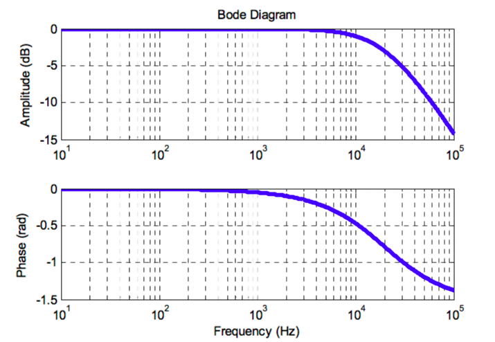
To plot more than one transfer function use the following syntax: bode(sys1,sys2,). The figure produced by the bode(sys) function can be copied and pasted into wordprocessors and other programs. H2 = fft(ym(t>=10)-2.2,NFFT)./fft(u(t>=10),NFFT) Constructing Bode Plots Using MatLAB The bode(sys) function can plot more than one transfer function on the same figure axis. I suggest you do the same thing when taking the FFT: L = length(ym(t>=10)) This gives the following plot (in Octave): You'll notice that I have discarded the time values before 10 and shifted the response values down by about 2.2. Num= %// Numerator of z-transform of impulse response of systemĭen= %// Denominator of z-transform of impulse response of system I want to plot bode diagram of the following system both using bode and fft: // System info num0 1 // Numerator of z-transform of impulse response of system den1 -0. Frequency is the logarithmic axis on both plots. Construction of Bode Plots 3 Bode plots consist of two individual graphs: a) a semilog plot of gain vs frequency b) a semilog plot of phase shift vs frequency. This same result could be achieved if the y-axis of the magnitude plot was shifted down 40 dB. The phase margin is now about -60 degrees. I looked at your data and compared it with the theoretical transfer function in the time-domain and it isn't a bad fit if you ignore some of the data: t = 1:length(u) Assume that you wanted to use Matlab in order to obtain Bode magnitude and phase plots for the following transfer function. Use MatLAB instructions it produce Bode plots of transfer functions. bode (100G) grid on title ( 'Bode Plot with Gain 100' ) As you can see, the phase plot is exactly the same as before, and the magnitude plot is shifted up by 40 dB (gain of 100). bode(sys) crea un diagrama de Bode de la respuesta en frecuencia de un modelo de sistema dinámico sys.


 0 kommentar(er)
